Waste heat recovery: introductory guide
Information about waste heat recovery and its potential as a low carbon heat source, as well as the process of capturing and utilising heat from industrial and commercial processes. The recovered heat can be used in a range of applications including heat networks.
3. Technical Characteristics
This section describes the main technical aspects of waste heat recovery and touches briefly on ambient heat. Topics covered are:
- Temperature ratings and grades of waste heat
- Ambient heat – sources and recovery
- Waste heat sources in various sectors
- Mine water geothermal
- Opportunities and challenges
- Options for reusing waste heat
- Heat recovery technologies
3.1 Temperature ratings and grades of waste heat
The most appropriate method of recovering waste heat from an industrial or commercial process will depend largely on the medium (gas or fluid) of the heat and its temperature. Heat emitted from industrial processes and other sources can be categorised or graded broadly as:
- High-grade heat: refers to heat above 400°C. This is heat typically lost from processes where a fuel is burnt and there is a reliance on high temperatures to catalyse chemical reactions, such as the production of cement. In most of these industries, generally as much heat as possible is recovered for re-use in the process.
- Medium-grade heat: heat between 100 and 400°C. For example, heat in flue gases emitted from an industrial gas boiler.
- Low-grade heat: refers to heat less than 100°C. Usually the temperatures are too low for heat to be used directly in industrial processes. It may still be useful, however, for space and water heating in domestic and commercial buildings or to increase the efficiency of some industrial processes. Low-grade heat can also be used as a source for heat pumps, which raise the temperature of the heat to a more suitable temperature, depending on the need. Low-grade industrial heat can also be captured from water used in cooling industrial processes.
3.1.1 Ambient heat – sources and recovery
Ambient heat is held within the air, ground, or water bodies such as rivers and the sea, and it generally originates from solar energy. Ambient heat presents sources of low-grade renewable heat that can be used, typically by heat pumps, to create higher temperature heat.
It is important to recognise the importance of ambient heat, as some applications, such as future heat networks, may rely on multiple sources of heat, including waste and ambient heat. An example is the Queens Quay development in Dumbarton which is served by a flagship district heat network that uses water source heat pumps to boost the temperature of ambient heat from the Clyde.
Another source of heat that is gaining interest across the UK is mine water. For more information on this, please refer to section 3.3.
3.2 Waste heat from sectors and services
Heat is created and often lost or wasted from a range of sectors and services. This waste heat varies in temperature (or grade – see above) and the medium in which it is conveyed. Sectors and sources and corresponding mediums and grades of heat are summarised in Table 1 below, and further detail is provided in Appendix B.
| Sector or source | Typical medium | Heat source grade |
|---|---|---|
| Manufacturing | ||
| Cement production | Flue gas | Medium / high |
| Paper & pulp manufacturing | Water | Medium |
| Food & drink manufacturing | Water | Low / medium |
| Distilleries | Flue gas | Low / medium |
| Chemical manufacturing | Water | Low |
| Services | ||
| Energy from waste | Flue gas | High |
| Industrial laundries | Flue gas | Low / medium |
| Electrical substations | Oil | Low |
| Wastewater treatment | Water / sewage | Low |
| Other | ||
| Hydrogen electrolysers | Air / liquid | Low |
| Hydrogen fuel cells | Air / liquid | Low |
| Supermarkets | Water | Low |
| Data centres & edge computing | Water | Low |
| Mine water | Water | Low |
3.3 Mine water geothermal
Unused, flooded, mine shafts can be used as a heat source. Over time, abandoned mines have filled with water which is constantly warmed by surrounding rocks. Temperatures range from 10 to 20°C and can reach 40°C at depths of around 1 km[9].
Scotland’s Midland Valley is thought to have 600 km3 of abandoned mines. Recorded mine water temperatures for boreholes in the Midland Valley generally range from 12 to 21°C, averaging at 17°C[10]. This may not accurately reflect higher temperatures that could occur in some of the deepest mine workings.
Currently, the two main methods to access mine water are:
1. Drilling boreholes, for which a permit is required from the Coal Authority, together with planning and SEPA permission. This is known as a ‘stand-alone’ scheme[11].
2. Via a Coal Authority mine water treatment scheme, at which water is brought to the surface and treated to remove impurities to protect drinking water and the environment. Where there is sufficient heat, the Coal Authority can provide access to this water for supply to a heat network. Permits are required from the Coal Authority and SEPA. This is known as a ‘bolt-on’ scheme.
There are two types of systems for using mine water heat:
1. Closed loop groundwater geothermal systems – which work by circulating a fluid around a closed pipe system, with a significant part of the pipe circuit located in a series of boreholes underground to absorb heat from the ground and groundwater and connected to a heat pump in an energy centre or in the building(s) to be heated or cooled.
2. Open loop geothermal systems - involve abstracting groundwater, which is used in a heat pump, and then the abstracted water is injected back into the ground.
The British Geological Survey’s Glasgow Observatory is a research facility designed for investigating shallow, low-temperature, mine water heat energy and potential heat storage resources. The observatory enables research into the questions that remain about this heat source, from size and sustainability to environmental impacts[12].
Heat from mine water contained in mine workings 150 m beneath the surface is being used to supply a heat network in Gateshead in the northeast of England. A water source heat pump recovers heat and distributes it through a 5 km long heat network. Currently this network supplies heat to 350 homes and various local buildings. This project is estimated to save 72,000 tonnes of CO2 over 40 years[13].
3.4 Waste heat recovery - opportunities and challenges
Every sector brings unique opportunities and challenges regarding waste heat recovery from the perspectives of recovering and reusing it.
There are common factors, however, which broadly apply across all sectors, some of which are set out in Table 2, below.
Table 2: Cross-sector opportunities and challenges for waste heat
Opportunities
- Can improve energy efficiency of the process or plant.
- Can reduce future heating costs.
- Can avoid costs to dispose of waste heat, e.g. cooling towers.
- Has potential to displace carbon intensive energy generation.
- Could mitigate the impact of future energy price increases and facilitate stable energy prices.
- Can generate an additional revenue stream
Challenges
- Payback periods can vary greatly.
- Potential disruption caused by installation of equipment.
- The ongoing operation and maintenance of equipment.
- Can be difficult to guarantee security of supply.
- There needs to be sufficient demand for heat to warrant the recovery.
- Ensuring heat recovery does not fundamentally alter core operations.
3.5 Options for reusing waste heat
Once a source of waste heat has been identified, it is important to identify an appropriate use or local demand for the heat. There may be multiple alternatives for its use, and each one should be assessed against key criteria before selecting the most appropriate option. This could include one or a combination of the options summarised below.
Reuse waste heat in-house: often the most viable option as it is usually the least complex and the loss of heat in distributing it can be minimised. This process is already seen in many energy intensive industries - for example, whisky distilleries recovering heat from hot water to pre-heat other stages of the distilling process. Typically, low-grade heat in industrial processes can only be used in some pre-heating processes or as input to other plant, such as industrial heat pumps[14].
Distribute waste heat to nearby consumers: selling waste heat directly to nearby heat consumers (e.g. swimming pools, residential developments etc.), without the need for a heat network. This can provide an additional source of income. Depending on the source, this can support decarbonisation plans and build a positive relationship with local communities.
Distribute waste heat to a nearby district heat network (DHN): heat is sold to a DHN operator, providing an additional income to the waste heat producer. The DHN operator then distributes this heat to consumers via a pipe network. This option has the advantage of being able to reach consumers further away from the source of waste heat, and may reduce costs for the DHN operator, potentially enabling it to provide heat at lower cost to consumers.
Waste heat used to generate electricity: if the temperature of the heat is sufficiently high, electricity generation may be possible by installing a steam turbine (or similar) to drive a generator. This electricity could be used inhouse or exported. Technologies which enable this are described in Section 3.7.
3.6 Technologies to recover waste heat for reuse
Heat recovery devices can be split into three main categories:
1. Heat recovery for reuse as heat – either in-house to pre-heat processes for example, or for exporting into a heat network
2. Heat recovery for electricity generation - for use on-site or for export to another site or to the grid.
3. Heat recovery and upgrade the temperature for use in a wider range of applications.
3.6.1 Heat exchangers
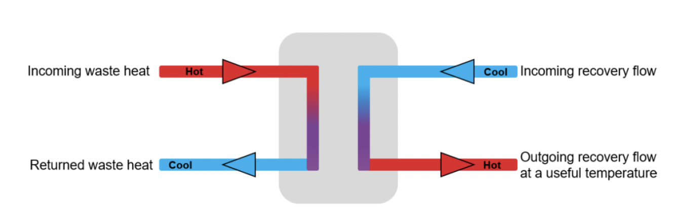
Heat exchangers are devices that enable the transfer of heat between two fluid mediums (i.e. liquids, air, or gases). Each fluid will be at a different temperature and in a different flow path to avoid mixing, resulting in a transfer of heat from the higher temperature fluid to the lower temperature fluid across a separating wall. The flow paths can be parallel, counterflow or crossflow[15]. Figure 1 shows a typical parallel flow arrangement.
There are different types of heat exchangers, which vary primarily depending on their physical arrangement. Common types are described in Table 3 below.
| Heat exchanger type | Description | Usual application and/or features |
|---|---|---|
| Plate | A series of thin plates with narrow spaces between them. The two fluids flow through alternate spaces, creating a transfer of heat between them via conduction through the plates. |
|
| Shell and tube | An array of tubes carrying a fluid are housed in an outer shell, creating a volume around the tubes which is filled with another fluid. The transfer of heat occurs between the fluids in the tubes and shell volume respectively. |
|
| Double pipe | Two concentric pipes, with a fluid in each, are used to transfer heat from one fluid to another. These are usually in a U-bend type design16. |
|
Heat exchangers are commonly used to capture and reuse low or medium grades of heat, and depending on the medium and grade of heat, they can be used in either primary or secondary systems:
- Primary systems – where a heat exchanger is used to transfer heat from the waste heat medium directly into the main medium for onward transmission and use.
- Secondary systems – where heat is recovered from the waste heat medium into a transfer fluid (such as water or oil) which then flows into a secondary heat exchanger to heat the main medium for use.
Some other commonly used devices which perform the duties of a heat exchanger are described briefly below.
3.6.2 Waste heat recovery boilers
A waste heat recovery boiler works much like a gas boiler. The key difference is that waste process heat rather than gas is used to heat a useful medium, typically water, which is moved and then usually evaporated for use in a different industrial process or for providing space heating or hot water generation.
3.6.3 Economisers
Economisers are like waste heat recovery boilers, although they serve different purposes. They are used to enhance the efficiency of various processes by preheating plant feedwater, which is used to generate a more useful product (typically steam).
The heat used in economisers is typically low-grade, although this is still sufficient to boost the efficiency of other plant. Using an economiser, for example, could result in feedwater entering a boiler at 50°C rather than 15°C.
3.6.4 Absorption chillers
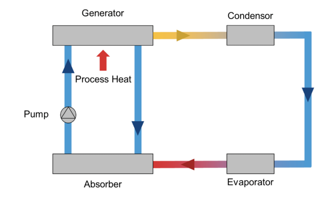
Absorption chillers use waste heat to produce cooling services (typically in the form of chilled water), rather than heat. They are well suited to industries that generate substantial volumes of waste heat but also require cooling.
Waste heat is used to evaporate and separate a water-lithium bromide mix. The water then condenses through a cooling tower and is fed into a different evaporator. A lithium bromide spray system then creates an attraction between the lithium bromide and water. This creates a vacuum which lowers pressure and causes the water to evaporate. This cools the water, which can then be used for cooling purposes.
Lithium-bromide is the most used mixing agent for the working fluid. Ammonia-water mixes are also suitable but are less common due to lower performance and safety concerns.
3.7 Technologies that recover heat for electricity generation
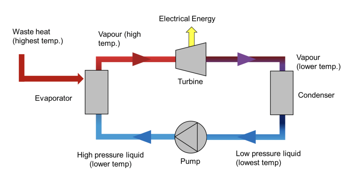
3.7.1 Direct steam to electricity systems - Steam Rankine Cycle (SRC)
This is the most common method of generating electricity from waste heat. A medium grade waste heat source is required (typically high temperature flue gases from a combustion process) and is passed through a heat exchanger to evaporate water into steam.
This steam is then passed through a turbine which rotates a shaft connected to an electricity generator. This process generates electricity which can be used locally or exported to other sites or the grid.
3.7.2 Direct steam to electricity systems - Organic Rankine Cycle
An Organic Rankine Cycle (ORC) system is like the SRC, but it uses an organic working fluid (e.g. methanol) rather than water. These organic fluids have a boiling point lower than that of water, creating an advantage in that the ORC can use lower grade sources of heat, with a minimum operating temperature around 80°C.
Although the ORC is not as efficient as the SRC, it can still be viable if a large volume of lower grade heat is consistently available. The simple schematic in Figure 5 is applicable to both the SRC and ORC.
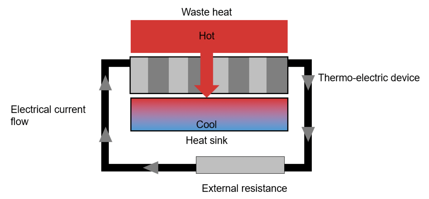
3.7.3 Thermoelectric generators
When a temperature difference exists between two semiconductors a voltage is generated (see Figure 6). This is the fundamental thermoelectric principle underpinning thermoelectric generators (TEG), which, unlike the devices described above, are solid state, with no moving parts.
TEGs (also known as Seebeck generators) are a flexible technology which can provide independent power at any location where waste heat can be used to create the necessary temperature difference. They have very low efficiencies, however, and are best suited to situations needing low amounts of power from a relatively maintenance free generator.
3.8 Technologies to recover and raise the temperature of waste heat
There are a range of technologies or systems used to recover heat from different mediums and to raise its temperature if required, typically using heat pumps.
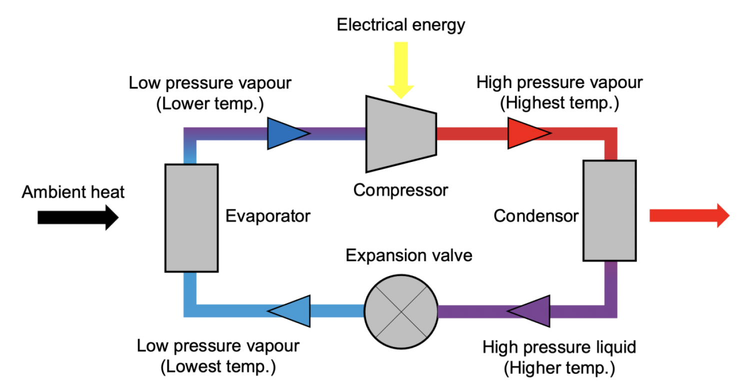
3.8.1 Using heat pumps to increase temperatures
In situations where heat transfer from waste or ambient heat sources does not create sufficiently high temperatures to suit the process or use for which it is intended, a heat pump can be used to boost the waste heat to higher temperatures.
As the electrification of heat expands as a major component of decarbonisation, the use of heat pumps will continue to increase. This is due to their ability to elevate waste and ambient sources to temperatures more suitable for a wider range of applications.
Heat pumps work in a way that is very similar to a domestic refrigerator. Refrigerant is evaporated using an ambient heat source and then compressed, which increases the refrigerant’s temperature. This hot refrigerant transfers its heat to the medium (usually water) that will be used in another process or system. The cooled refrigerant condenses back into a liquid before expanding back into a vapour where the cycle repeats. This is shown in Figure 7 below.
Heat pumps can be classified by the source of ambient or waste heat that is used to create useful heat. The three main types are air source heat pumps (ASHPs), ground source heat pumps (GSHPs) and water source heat pumps (WSHPs).
Whilst efficiencies of heat pumps vary as a function of factors such as the temperatures of the heat source, their minimum efficiencies are generally at least twice that of using electricity directly for heating, reducing the running cost and impact on grid capacity. In other words, a heat pump uses a unit of electricity (to drive the compressor) to create two or more units of heat.
Each type of heat pump system has different infrastructure requirements, depending on the heat source being exploited. Examples of these are shown in Table 4.
Table 4: Typical heat pump efficiencies and infrastructure requirements
Heat pump type
ASHP
Typical efficiency (output vs. input energy)
250% to 350%
Typical efficiency (output vs. input energy)
- Units need to be located externally and unobstructed to allow for large amounts of air to be drawn through and the heat extracted.
- Large units can be noisy, so need to be considered carefully.
Heat pump type
GSHPs and WSHPs
Typical efficiency (output vs. input energy)
400% (GSHPs)
350% (WSHPs)
Typical efficiency (output vs. input energy)
- Extensive groundwork can be required to install boreholes or pipe coils.
- If water is taken direct from a source, appropriate licenses will be required, and the technical complexity of the system can increase.
Contact
Email: heatnetworks@gov.scot
There is a problem
Thanks for your feedback